Image impedance
Image impedance is a concept used in electronic network design and analysis and most especially in filter design. The term image impedance applies to the impedance seen looking into a port of a network. Usually a two-port network is implied but the concept can extended to networks with more than two ports. The definition of image impedance for a two-port network is the impedance, Zi 1, seen looking into port 1 when port 2 is terminated with the image impedance, Zi 2, for port 2. In general, the image impedances of ports 1 and 2 will not be equal unless the network is symmetrical (or anti-symmetrical) with respect to the ports.
- Parts of this article or section rely on the reader's knowledge of the complex impedance representation of capacitors and inductors and on knowledge of the frequency domain representation of signals.
Derivation


.svg.png)
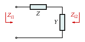
As an example, the derivation of the image impedances of a simple 'L' network is given below. The L network consists of a series impedance, Z, and a shunt admittance, Y.
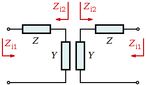
The difficulty here is that in order to find Zi 1 it is first necessary to terminate port 2 with Zi 2. However, Zi 2 is also an unknown at this stage. The problem is solved by terminating port 2 with an identical network: port 2 of the second network is connected to port 2 of the first network and port 1 of the second network is terminated with Zi 1. The second network is terminating the first network in Zi 2 as required. Mathematically, this is equivalent to eliminating one variable from a set of simultaneous equations. The network can now be solved for Zi 1. Writing out the expression for input impedance gives;
and solving for Zi 1,
Zi 2 is found by a similar process, but it is simpler to work in terms of the reciprocal, that is image admittance Yi 2,
Also, it can be seen from these expressions that the two image impedances are related to each other by;
Measurement
Directly measuring image impedance by adjusting terminations is inconveniently iterative and requires precision adjustable components to effect the termination. An alternative technique to determine the image impedance of port 1 is to measure the short-circuit impedance ZSC (that is, the input impedance of port 1 when port 2 is short-circuited) and the open-circuit impedance ZOC (the input impedance of port 1 when port 2 is open-circuit). The image impedance is then given by,
This method requires no prior knowledge of the topology of the network being measured.
Usage in filter design
When used in filter design, the 'L' network analysed above is usually referred to as a half section. Two half sections in cascade will make either a T section or a Π section depending on which port of the L section comes first. This leads to the terminology of Zi T to mean the Zi 1 in the above analysis and Zi Π to mean Zi 2.
Relation to characteristic impedance
Image impedance is a similar concept to the characteristic impedance used in the analysis of transmission lines. In fact, in the limiting case of a chain of cascaded networks where the size of each single network is approaching an infinitesimally small element, the mathematical limit of the image impedance expression is the characteristic impedance of the chain. That is,
The connection between the two can further be seen by noting an alternative, but equivalent, definition of image impedance. In this definition, the image impedance of a network is the input impedance of an infinitely long chain of cascaded identical networks (with the ports arranged so that like impedance faces like). This is directly analogous to the definition of characteristic impedance as the input impedance of an infinitely long line.
Conversely, it is possible to analyse a transmission line with lumped components, such as one utilising loading coils, in terms of an image impedance filter.
Transfer function
The transfer function of the half section, like the image impedance, is calculated for a network terminated in its image impedances (or equivalently, for a single section in an infinitely long chain of identical sections) and is given by,
where γ is called the transmission function, propagation function or transmission parameter and is given by,
The term represents the voltage ratio that would be observed if the maximum available power was transferred from the source to the load. It would be possible to absorb this term into the definition of γ, and in some treatments this approach is taken. In the case of a network with symmetrical image impedances, such as a chain of an even number of identical L sections, the expression reduces to,
In general, γ is a complex number such that,
The real part of γ, represents an attenuation parameter, α in nepers and the imaginary part represents a phase change parameter, β in radians. The transmission parameters for a chain of n half sections, provided that like impedance always faces like, is given by;
As with the image impedance, the transmission parameters approach those of a transmission line as the filter section become infinitesimally small so that,
with α, β, γ, Z, and Y all now being measured per metre instead of per half section.
Relationship to two-port network parameters
ABCD parameters
For a reciprocal network (AD−BC=1), the image impedances can be expressed[1] in terms of ABCD parameters as,
- .
The image propagation term, γ may be expressed as,
- .
Note that the image propagation term for a transmission line segment is equivalent to the Propagation constant of the transmission line times the length.
| Image filter sections | ||||||||||||||||||||||||||||||||||||||||||
|---|---|---|---|---|---|---|---|---|---|---|---|---|---|---|---|---|---|---|---|---|---|---|---|---|---|---|---|---|---|---|---|---|---|---|---|---|---|---|---|---|---|---|
|
||||||||||||||||||||||||||||||||||||||||||
| ||||||||||||||||||||||||||||||||||||||||||
| ||||||||||||||||||||||||||||||||||||||||||
See also
References
- Matthaei, Young, Jones Microwave Filters, Impedance-Matching Networks, and Coupling Structures McGraw-Hill 1964


.svg.png)


.svg.png)

.svg.png)