Anisotropic filtering

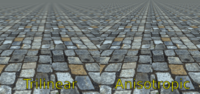
In 3D computer graphics, anisotropic filtering (abbreviated AF) is a method of enhancing the image quality of textures on surfaces of computer graphics that are at oblique viewing angles with respect to the camera where the projection of the texture (not the polygon or other primitive on which it is rendered) appears to be non-orthogonal (thus the origin of the word: "an" for not, "iso" for same, and "tropic" from tropism, relating to direction; anisotropic filtering does not filter the same in every direction).
Like bilinear and trilinear filtering, anisotropic filtering eliminates aliasing effects, but improves on these other techniques by reducing blur and preserving detail at extreme viewing angles.
Anisotropic filtering is relatively intensive (primarily memory bandwidth and to some degree computationally, though the standard space–time tradeoff rules apply) and only became a standard feature of consumer-level graphics cards in the late 1990s. Anisotropic filtering is now common in modern graphics hardware (and video driver software) and is enabled either by users through driver settings or by graphics applications and video games through programming interfaces.
An improvement on isotropic MIP mapping

From this point forth, it is assumed the reader is familiar with MIP mapping.
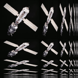
If we were to explore a more approximate anisotropic algorithm, RIP mapping, as an extension from MIP mapping, we can understand how anisotropic filtering gains so much texture mapping quality. If we need to texture a horizontal plane which is at an oblique angle to the camera, traditional MIP map minification would give us insufficient horizontal resolution due to the reduction of image frequency in the vertical axis. This is because in MIP mapping each MIP level is isotropic, so a 256 × 256 texture is downsized to a 128 × 128 image, then a 64 × 64 image and so on, so resolution halves on each axis simultaneously, so a MIP map texture probe to an image will always sample an image that is of equal frequency in each axis. Thus, when sampling to avoid aliasing on a high-frequency axis, the other texture axes will be similarly downsampled and therefore potentially blurred.
With RIP map anisotropic filtering, in addition to downsampling to 128 × 128, images are also sampled to 256 × 128 and 32 × 128 etc. These anisotropically downsampled images can be probed when the texture-mapped image frequency is different for each texture axis. Therefore, one axis need not blur due to the screen frequency of another axis, and aliasing is still avoided. Unlike more general anisotropic filtering, the RIP mapping described for illustration is limited by only supporting anisotropic probes that are axis-aligned in texture space, so diagonal anisotropy still presents a problem, even though real-use cases of anisotropic texture commonly have such screenspace mappings.
In layman's terms, anisotropic filtering retains the "sharpness" of a texture normally lost by MIP map texture's attempts to avoid aliasing. Anisotropic filtering can therefore be said to maintain crisp texture detail at all viewing orientations while providing fast anti-aliased texture filtering.
Degree of anisotropy supported
Different degrees or ratios of anisotropic filtering can be applied during rendering and current hardware rendering implementations set an upper bound on this ratio. This degree refers to the maximum ratio of anisotropy supported by the filtering process. For example, 4:1 (pronounced “4-to-1”) anisotropic filtering will continue to sharpen more oblique textures beyond the range sharpened by 2:1.
In practice what this means is that in highly oblique texturing situations a 4:1 filter will be twice as sharp as a 2:1 filter (it will display frequencies double that of the 2:1 filter). However, most of the scene will not require the 4:1 filter; only the more oblique and usually more distant pixels will require the sharper filtering. This means that as the degree of anisotropic filtering continues to double there are diminishing returns in terms of visible quality with fewer and fewer rendered pixels affected, and the results become less obvious to the viewer.
When one compares the rendered results of an 8:1 anisotropically filtered scene to a 16:1 filtered scene, only a relatively few highly oblique pixels, mostly on more distant geometry, will display visibly sharper textures in the scene with the higher degree of anisotropic filtering, and the frequency information on these few 16:1 filtered pixels will only be double that of the 8:1 filter. The performance penalty also diminishes because fewer pixels require the data fetches of greater anisotropy.
In the end it is the additional hardware complexity vs. these diminishing returns, which causes an upper bound to be set on the anisotropic quality in a hardware design. Applications and users are then free to adjust this trade-off through driver and software settings up to this threshold.
Implementation
True anisotropic filtering probes the texture anisotropically on the fly on a per-pixel basis for any orientation of anisotropy.
In graphics hardware, typically when the texture is sampled anisotropically, several probes (texel samples) of the texture around the center point are taken, but on a sample pattern mapped according to the projected shape of the texture at that pixel.
Each anisotropic filtering probe is often in itself a filtered MIP map sample, which adds more sampling to the process. Sixteen trilinear anisotropic samples might require 128 samples from the stored texture, as trilinear MIP map filtering needs to take four samples times two MIP levels and then anisotropic sampling (at 16-tap) needs to take sixteen of these trilinear filtered probes.
However, this level of filtering complexity is not required all the time. There are commonly available methods to reduce the amount of work the video rendering hardware must do.
The anisotropic filtering method most commonly implemented on graphics hardware is the composition of the filtered pixel values from only one line of MIP map samples, which is referred to as "footprint assembly".[1][2]
Performance and optimization
The sample count required can make anisotropic filtering extremely bandwidth-intensive. Multiple textures are common; each texture sample could be four bytes or more, so each anisotropic pixel could require 512 bytes from texture memory, although texture compression is commonly used to reduce this.
A video display device can easily contain over two million pixels, and desired application framerates are often upwards of 60 frames per second. As a result, the required texture memory bandwidth may grow to large values. Ranges of hundreds of gigabytes per second of pipeline bandwidth for texture rendering operations is not unusual where anisotropic filtering operations are involved.
Fortunately, several factors mitigate in favor of better performance:
- The probes themselves share cached texture samples, both inter-pixel and intra-pixel.
- Even with 16-tap anisotropic filtering, not all 16 taps are always needed because only distant highly oblique pixel fills tend to be highly anisotropic.
- Highly Anisotropic pixel fill tends to cover small regions of the screen (i.e. generally under 10%)
- Texture magnification filters (as a general rule) require no anisotropic filtering.
See also
References
- ↑ Schilling, A.; Knittel, G.; Strasser, W. (May 1996). "Texram: a smart memory for texturing". IEEE Computer Graphics and Applications. 16 (3): 32–41. doi:10.1109/38.491183.
- ↑ Schilling, A.; Knittel, G., US 6236405 "System and method for mapping textures onto surfaces of computer-generated objects" May 22, 2001